A popular modification to the 3SGTE engine is to add crank and cam sensors and remove the factory distributor. Because of their affordable cost and flexible mounting options, many people use Cherry Hall sensors in this application. This post discusses how to wire Cherry sensors to your Elite unit.
If you are replacing factory distributor sensors and have an existing PNP unit, you have a little bit of wiring to do first. The existing wiring uses 3 wires only (trigger, home, and a shared sensor ground). The Cherry sensors get 3 wires each (power, ground, and signal).
First, obtain the data sheet for your sensors and read it. In this post we’ll talk about the GS1005 sensor as an example. From the data sheet, we can tell that the GS1005/6/7 sensors can be powered by anywhere from 5-24 volts and are internally regulated. this is useful information; it means we can use the standard car voltage to power the sensors. In a Haltech wiring loom, this will be the red wires in each of the 4-conductor shielded sheaths.The Yellow wires in these sheaths are for the sensor signal, and the Green wires are used for signal/sensor ground.
The Cherry sensor wiring is as shown below: Brown is voltage supply, Blue is ground, and Black is sensor output.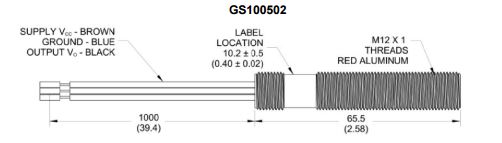
So you will wire
- Brown from the Cherry sensor to Red from the Elite 4-conductor sheath;
- Blue from the Cherry sensor to Green in the Elite 4-conductor sheath, and
- Black from the Cherry sensor to Yellow in the Elite 4-conductor sheath.
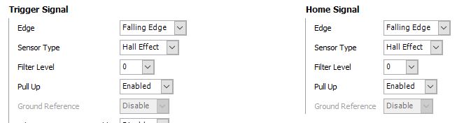
Now, check your settings in the ESP software; it should resemble the figure below (Falling Edge, Hall Effect, Pull-Up Enabled).