Install Cherry Hall Sensors in your Elite PNP system

A popular modification to the 3SGTE engine is to add crank and cam sensors and remove the factory distributor. Because of their affordable cost and flexible mounting options, many people use Cherry Hall sensors in this application. This post discusses how to wire Cherry sensors to your Elite unit.

If you are replacing factory distributor sensors and have an existing PNP unit, you have a little bit of wiring to do first. The existing wiring uses 3 wires only (trigger, home, and a shared sensor ground). The Cherry sensors get 3 wires each (power, ground, and signal).

First, obtain the data sheet for your sensors and read it. In this post we’ll talk about the GS1005 sensor as an example.  From the data sheet, we can tell that the GS1005/6/7 sensors can be powered by anywhere from 5-24 volts and are internally regulated. this is useful information; it means we can use the standard car voltage to power the sensors. In a Haltech wiring loom, this will be the red wires in each of the 4-conductor shielded sheaths.The Yellow wires in these sheaths are for the sensor signal, and the Green wires are used for signal/sensor ground.

The Cherry sensor wiring is as shown below: Brown is voltage supply, Blue is ground, and Black is sensor output.

So you will wire

  • Brown from the Cherry sensor to Red from the Elite 4-conductor sheath;
  • Blue from the Cherry sensor to Green in the Elite 4-conductor sheath, and
  • Black from the Cherry sensor to Yellow in the Elite 4-conductor sheath.

Now, check your settings in the ESP software; it should resemble the figure below (Falling Edge, Hall Effect, Pull-Up Enabled).


Connect an Aftermarket Ignition to your Elite

This article discusses how to connect and run an aftermarket ignition system with your Haltech Elite. The example we will use is the MDS DIS-4 Plus, but the concepts are the same for other manufacturer’s units. Basically, the interaction between the Elite and the aftermarket ignition system is exactly this: the Elite tells the aftermarket system when to fire. No more, no less. The Haltech does not supply power to the ignition system or the coils, it tells the ignition when to fire.

The steps are, in order,

  1. Install the unit according to the manufacturers instructions
  2. Connect the Ignition output wires from the Haltech to the proper wire on the ignition system, and
  3. Set up the appropriate coil parameters in the ESP software.

When wiring a DIS-4 Plus to an Elite 3SGTE PNP system, the connections are as follows:

  • White wire from DIS-4 harness (Trigger 1) to Yellow/Black wire from Elite (IGN1)
  • Green wire from DIS-4 harness (Trigger 2) to Yellow/Red wire from Elite (IGN2)
  • Yellow wire from DIS-4 harness (Trigger 3) to Yellow/Orange wire from Elite (IGN3)
  • Violet wire from DIS-4 harness  (Trigger 4) to Yellow/Green wire from Elite (IGN4)

(Please note, these are the wire colors in the MSD documentation at the time of this writing, please double-check your own wiring)

OK, you’re installed, you’re wired, what next? You need to set up the ESP software for your ignition system. With the key on and the ECU connected, under Main Setup -> Ignition, make sure you have Direct Fire enabled, and Edge and Dwell Mode as appropriate for your ignition system (for the DIS-4, use Rising Edge and Constant Charge).

You should be good to go.

Haltech Elite for 3SGTE GenII/III – Getting Started Guide

Caution!

Read these instructions and the Haltech Users Manual (included with the Haltech ESP software) first before installing and tuning.
Installation should only be attempted by an experienced mechanic. It is recommended you disconnect the battery (-) terminal before installation. Tuning should be performed by a professional tuner on a dynamometer, with a wideband O2 sensor.
NEVER ATTEMPT TO DRIVE AND TUNE AT THE SAME TIME!
It is strongly recommended that you install this system on a known working, running engine with spark plugs and ignition components within manufacturers specifications.
Legal for off-road use only. Remember – you are responsible for what you do to your engine.

OK, with that out of the way, let’s get started on getting your system safely installed and running.

Other Parts You May Need:

If you are installing on a GenII MR2 Turbo and desire to run in speed-density mode (using a map sensor), you need to install a Manifold Air Temperature sensor. Your kit includes a pre-wired MAT sensor. To install the MAT sensor in the intake manifold (in place of a cold-start injector), you need to purchase or fabricate a block-off plate. Contact us for details.

To perform in-cabin tuning, you will need to run a USB cable into the cabin. If your system included customization options (e.g., wiring for an electronic boost controller, external ignition or non-stock sensors), please read and follow the manufacturer’s instructions (as well as any custom instructions you receive from us) in addition to this document.

Installation (MR2 Turbo)

Remove the rear trunk carpet/cover on the rear firewall, and expose the stock ECU and wiring. Undo the bolts holding the stock ECU in place. Unplug the three connectors wired to the stock ECU. Remove the stock ECU and set aside.

Install the MAT sensor (if applicable). Run a vacuum line for the boost sensor (if applicable).

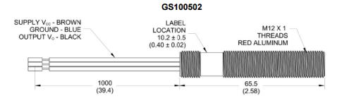
Install the interface unit and the Elite in the trunk in place of the stock ECU. Connect to your laptop USB cable.

Install and connect any optional wiring accessories.

Reconnect your battery.
That’s the “plug” part of “plug and play.” 

Getting Started
0. If you are installing for the first time, or have made significant changes to the engine, I recommend attaching a battery charger to your battery before getting started. Few things are as frustrating as having your battery die while trying to get your engine running.

1. Load the Haltech ESP software on a laptop computer. A USB key comes with your system, or you can always download the latest version of the Haltech software at http://www.haltech.com/downloads-2/ecu-software-firmware/

2. Run the ESP software. 

3. Connect to the Elite (turn key On, when it asks if you want to connect click OK)

4. If you requested we open the box and load your base map for you, skip this step. Otherwise – after the ECU initializes, load the startup map. Locate the startup map on your computer (it was likely sent to you as an email attachment). Copy the file to your Haltech\Ecu Maps folder. From the Haltech ESP user interface, select File -> Upload Map and select your startup map.

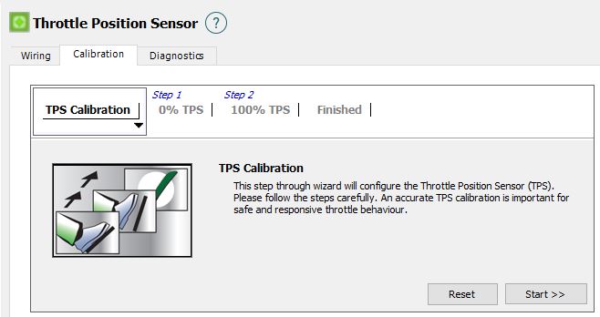
5. Calibrate the TPS – Select Setup -> Main Setup -> Functions -> Throttle Position Sensor and open the Calibration tab. Run the calibration wizard.


Steps 6 & 7 temporarily disable your engine so you can safely sync the ignition timing.

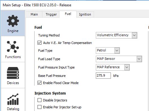
6. Check that injectors are OFF (not Enabled). Select Setup -> Main Setup -> Fuel  from the menu, and check the box marked “Disable Injectors” and click “Apply.”

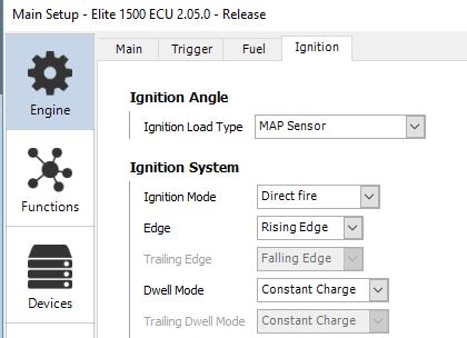
7. Lock Timing at 10° – From Main Setup, choose the Ignition tab and select “Always On” in the Lock Mode dropdown box.

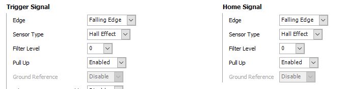
8. Using a timing light, turn the engine over (it won’t start, because you disabled the injectors in step #6). Verify the timing (at 10°). If it is off, adjust the distributor and/or the TDC offset angle in the Trigger setup screen. If you are running a stock distributor, keep in mind that a LOT of 3s engines on the road have their cam timing off by as much as 1 (belt) tooth, this will require an approximately 15° change in  offset angle. Personally, I would get the cam timing right before continuing, but that is up to you. NOTE: if you are running a separate 3rd-party crank sensor, you have some work to do in step 8. I can’t guess (from here) the relationship between where the missing teeth on your crank wheel pass the crank sensor and TDC on the Combustion Stroke. If the crank wheel is keyed (installs in the same position on every engine) and the supplier has provided guidance on position, use that guidance as a starting point for the offset. Keep in mind 2 things though – (1) even a keyed, consistent crank wheel is independent of engine stroke, so you could be off by 360°, and (2) whatever you do you want the TDC Offset value to be larger than the largest advance angle you plan to run (for a 2nd/3rd gen 3SGTE I want the TDC offset angle to always be 55° or more). Hint: if your value works out to under your target max advance, use (720 – value) instead.

9. Unlock the timing – From Main Setup, choose the Ignition tab and select “On During Flood Clear Only” in the Lock Mode dropdown box.

10. Enable the injectors – Select Setup -> Main Setup -> Fuel  from the menu, un-check the box marked “Disable Injectors” and click “Apply.”

11. Start tuning. Turn off all auxiliary maps and tune the fuel map first, tune from low load to high load, and adjust from rich to lean (not lean to rich). Next tune the timing map, again, go from conservative values and slowly add timing advance. Finally, enable and tune your choice of auxiliary maps.

Parts Bin Garage/Shop Stereo

I end up spending a lot of time in the garage or the driveway, and sometimes it’s nice to have soothing music in the background – and other times it’s nice to have adrenaline-pumping rock assaulting my ears. I used to have a moderate-sized old boombox for that purpose, but my son took it camping… then threw it out when the batteries died (as if I could make this up!). Parts Express had a good sale going on a little while back, I was about to commit to buying a little amp with an integrated USB port, and was searching eBay for some Bose or Cambridge Soundworks Sat/Sub combos – because anything that is “just” 2 channels is pretty much a giveaway these days. I was getting ready to pull the trigger and buy, when I thought to myself, “Nah – let’s see how close to free we can do this.” So, off to the parts bin.

I suppose it helps to have pack-rat inclinations, I save a lot of old stuff that I should probably throw away.

Speakers: I ran across a set of 6×9″ Polk “triaxial” speakers (in, of all things, an Infinity 10.1d sub box) in the basement recently. These have probably been sitting in my basement for 12+ years, I had briefly installed them in a 1994 Accord. I kept them when I sold the car because they sounded great and I was sure I’d put them in some family member’s car. In spite of the seriously-compromised design of a 6×9 cone with 2 drivers mounted in front of it, they will do the job nicely for my garage. While I was going to stay cheap and build enclosures out of plywood scraps, I splurged and bought a set of Scoshe 6×9″ enclosures on Amazon. Considering that $24.99 was the total outlay for this project, money well-spent.

Sound source: If you’ve worked on multiple project cars, chances are you’ve come across a head unit or two you didn’t need. My latest project car had a Sony headunit with a USB input, bluetooth, bells and whistles galore. Not good enough for the “no compromises” MR2 Spyder project, but just fine for the garage. I hooked it up to my bech power supply and one of the polk-in-scoshe speakers to test; works good, sounds good.

Power: Of course, there’s no 12v power source in the garage to run a car headunit. So we need a power supply. The purist in me kicked in, I started searching for linear 12v regulated power supplies. Hmmm. Tons of inexpensive power supplies out there, but anything with some iron in it is still expensive (see “purist” and “linear” earlier in this paragraph). Aha – I remembered I had an old regulated power supply somewhere in a box, my father-in-law used it in the 1970s to power his CB radio (again, I can’t make this up). I even remembered where it was. Took it out, dusted it off, plugged it in and… nothing. Would not run the Sony. A quick check with a voltmeter showed this 40-yr-old 12v power supply was not outputting…. 8.63v. So, let’s open it up and take a look…. really simple design…. cross-reference the one power transistor….. order up some replacement parts and fix it, right? Well…… nah. Let’s not buy parts and spend time. I’ll keep the transformer (see “pack rat,” above) and toss the rest. There are alternatives.

Alternative # 1 – I have a bunch of desktop computer power supplies, let’s look through those. I found 3. Smallest one is 440w output. hmmmm, that’s way overkill (on the bench supply the Sony cranked up high was drawing under 1A @ 13.2v). I just don’t like the idea of running a 440w PS to power a maybe 15w draw. Plus, there’s the heat and the fan… let’s move on.

Alternative #2 – Laptop power supply. A quick search of my bin of AC/DC plug-in converters found a charger brick from an old Panasonic Toughbook: 14v @ 5A. Perfect. Clip the plug end, plug ‘er in and….. we have tunes. Well worth the $25, and I made some space in the parts bins to boot!


polk

Resurrect the MiniDV Camcorder

So many old video tapes, and no way to watch them. I think we got our first camcorder in ’88, it was a Sony Video8 (not Hi8 or Digital8, as those had not yet been invented). It was impressive, too — stereo audio, autofocus, and about 1/3 the size of the VHS camcorders that were the norm those days (yes, you had to physically place a VHS tape in a device, put it on your shoulder and record….. good times). There are a dozen or so Video8 tapes kicking about, although I had the foresight to transfer them to Beta, and later to VHS. But more about Video8 later.

Fast forward (see what I did there?) 11 years, the expensive stereo Video8 camcorder had been sitting in a closet for years with a tape in it, and it was just completely hosed. I discovered this the day before a big family vacation, and used it as an excuse to run out and buy a state-of-the-art MiniDV digital camcorder, the JVC DVM50.

Impressive machine for it’s time. Maybe 1.5 times the size of my fist, 32- or 48-khz audio sampling, it took digital stills (yes, my first digital camera) and had a firewire port to connect to a PC. Lots of captured memories – a few even sent back to the computer – and another dozen or so tapes hanging around the house. The batteries (yes, they were LiOn batteries – definitely state-of-the-art) have long since died, and the charger/ac adapter was lost years ago. So, how can I get my videos?

Well, time to make a new ac adapter. Let’s start with the 17-yr-old original battery.

Those warnings weren’t meant for me, were they? 🙂  Note the +, T and – marking on the battery terminals. The “T” stands for “thermistor,” which is a safety measure intended to tell chargers to stop charging if the battery pack gets too hot – that’s pretty cool, but for our purposes totally irrelevant. Note also the voltage output rating (7.2v). A quick search indicates that a 7.2v Lithium ion battery pack will normally vary between about 8.4v (100% charged) to somewhere in the mid-6-volt range fully depleted. So we are going to shoot for reaplacing this with something in the 7.5-8v range.

The first step is to carefully pry open the battery pack plastic – it’s not easy, and it requires some care to not demolish the plastic. No need to be real neat about it, though, we just need enough of the original shape so the camcorder thinks it has a battery installed. After opening the case, cut out the leads going to the battery cells and pry out the batteries (in this case they were glued in).

Here’s where it’s good that we made note of the + and – terminals. The next step is to find a suitable ac/dc adapter. I have a shoe box full of old adapters from long-discarded devices, after digging around I found some candidates. I also decided to test them before letting them power the camcorder, so I brought out the trusty voltmeter, plugged ’em in and measured. Hmmm, the most promising adapter, marked 7.5v/1a, was putting out 10.52v. That ain’t right, is it?

Luckily, I know how to use a search engine. Searching for “voltage divider calculator” gave me a nice cookbook on how to use 2 resistors to reduce that 10.5v down to my desired range. And I happen to have a bunch of resistors around, so this was easy enough to try. Before soldering everything up, I tested it again and got…. huh. 3.2v. That ain’t right either, is it? I fussed with the resistor values a bit, and got similar results. Then I thought it through. With no load, the adapter was putting out 10.5v. Add a load, it drops. At 1A, it’s rated at 7.5v.  A little more searching, and a little more experimenting, and I confirmed it (more or less, I measured it at 7.63, but who is counting, right?).  So, all that remained was soldering the wires from the adapter to the terminals of our disassembled battery pack.

Re-assemble, using some hot glue as strain relief, then re-test to the terminals. And… working camcorder, ready to transfer my old tapes to the cloud.


As with any of my posts, try this at home (or anywhere else) at your own risk.